

The RTC360 from Leica is one of the best laser scanning units on the market. It is fast, accurate for medium ranges, user friendly, lightweight, offers decent point cloud colorization, and it is versatile in the field. What more could you expect from a terrestrial scanner? Well, I have never heard of a product that is designed to satisfy every customer. Despite all its features, the RTC360’s Achilles heel is the lack of a dual-axis compensator. For some, this can be a deal breaker. For others, this is just a small inconvenience. Most will adapt their existing workflows to accommodate this amazing piece of hardware.
The unit is equipped with an IMU that “levels” the data. However, its 3’ accuracy does not satisfy everyone’s requirements. A tilt of 3’ means accumulating 8.7mm of error at every 10 meters. If a building is 100m long the resulting registration could be off level by 87.3mm (3.43 in). In my world that is not acceptable. So, what options do we have to ensure the registered point clouds meet a higher levelness?
The default solutions are to pair the RTC360 with Leica P series scanner (or any other unit equipped with a survey grade dual-axis compensator) or use survey control. These solutions could be expensive if you do not have an in-house surveyor or own a Leica P series, Sometimes, on small projects, the cost of setting control can be higher than the cost of laser scanning.
what if I told you there is another solution? A solution that is faster, affordable, does not require additional staff, and ensures an accuracy that would satisfy most small and medium size projects.
Since the goal of each project is to have leveled data that meets a defined accuracy threshold, the solution is to introduce a new instrument into our workflow that excels at defining a work-plane that is leveled.
The concept of this solution is straightforward: use the leveled work-plane as a reference when finalizing the registration using Cyclone Core. The question is: how are we referencing this work-plane in the field, as well as in the office? Here is the step-by-step workflow.
Step 1: Select an instrument
There is large selection of instruments on the market. Their price can range between $500 and $2,000. Below are the criteria for selecting an optimal instrument that would satisfy most needs. If higher accuracy and range take priority over price, than I would recommend a top-of-the-line rotary self-leveling laser kit.

Step 2: determine setup locations
The self-leveling laser should be used at every building level. The targets at one of the levels will be used to adjust the registration and the targets at the remaining levels as check points.
Ideally you would position the self-leveling laser in a location that meets the following guidelines:
The line of sight is more than 60 ft– i.e. lobby, event hall, warehouse, intersection of corridors (most common)
Most walls face the instrument
The space allows for a homogenous distribution of the targets
Step 3: Place paper targets
Place at least 5 targets per location at various distances from the instrument.
Spread the targets equally around the instrument.
Avoid placing more than 2 targets on the same vertical plane.
The targets should be facing the instrument as much as possible.

Step 4: Capture the targets
All the targets should be captured from a single scan station. Hence, we recommend occupying the position of the self-leveling laser instrument.
Run a full scan at the highest resolution possible – this step will ensure easy target extraction and legibility of the labels.

Step 5: Extract the targets
The targets should only be extracted once to avoid target merging and increase the accuracy of their position.
For extraction use the scan station that occupied the position of the self-leveling laser instrument.
Visually check the accuracy of the target extraction.
Repeat this process for each level.
Define a distinct naming convention for each level. It will be helpful later.
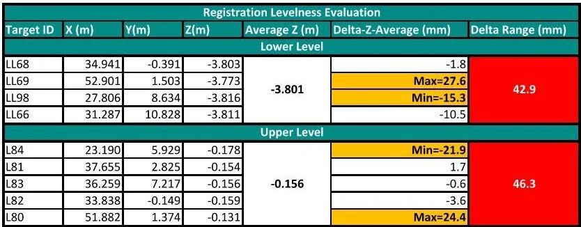
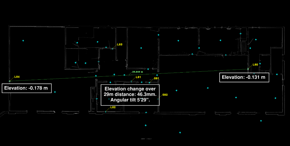
Step 6: Evaluate the levelness of the registration
Sometimes we get lucky and realize the scan station we chose to be the registration “homescan” is fairly leveled and no further action is needed. With the help of the extracted targets, we will check the levelness of the current registration.
Export the all the targets to a CSV file format.
Sort the points by level and delete the irrelevant points. This is where the naming convention comes in handy.
For each level calculate an average elevation for the corresponding targets.
In a new column subtract the average elevation from the elevations of each target.
In the next column calculate the difference between the minimum and maximum values calculated in the previous column.
Analyze the results. If the elevation ranges calculated in the last column MEET THE PROJECT’S LOA AND THEY ARE CONSISTENT FOR ALL PROJECT LEVELS, then no further leveling is required.
Step 7: Set coordinate system based on points
We will be leveling the registration by defining a new coordinate system. As I mentioned above, this workflow is only possible in Cyclone Core.
Select five points that will be used in setting up the new coordinate system. Please note that the selection order matters.
Point 1- Reference Point; Pick one of the leveled targets. This point will represent an offset from the origin, or it can be defined as the origin. The X, Y, Z reference values are defined by the user.
Point 2- Elevation Point 1; Pick one of the leveled targets. This point will be one of the points defining the leveled plane.
Point 3- Elevation Point 2; Pick one of the leveled targets. This point will be one of the points defining the leveled plane.
Point 4- Azimuth Point; Pick one the leveled targets or any other point to define the direction of the azimuth vector.
Point 5- Top point; Pick any point located above the Point 1. This point will define the positive direction of the Z axis.
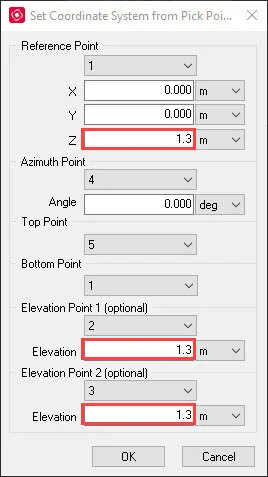
Avoid situations where point 1, 2, and 3 are colinear. Ideally these three points should define an equilateral triangle. In practice this will be hard to achieve. However, if the three points define a triangle close to the ideal shape, you will get optimal results.
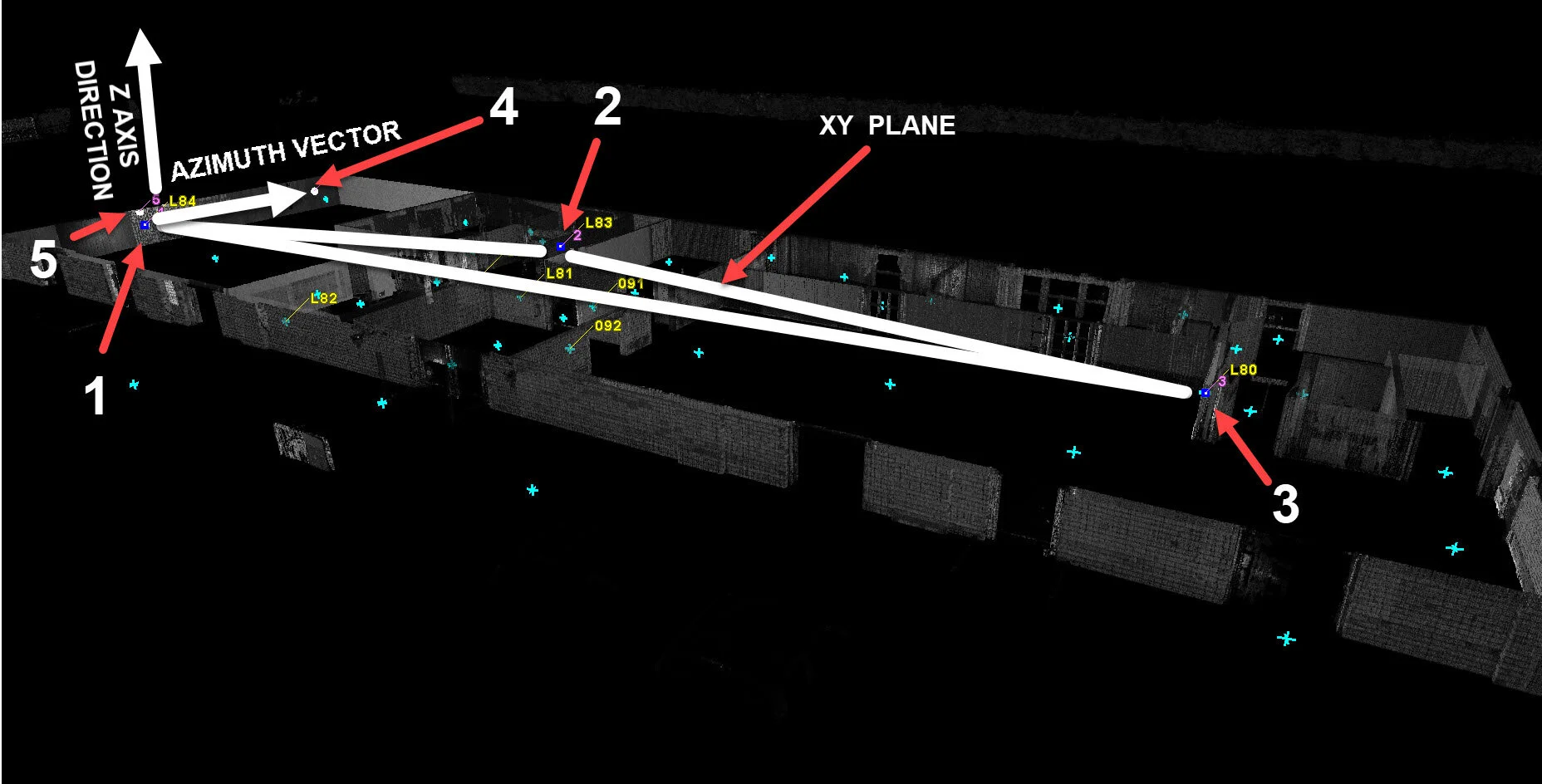
Once the new coordinate system is set, verify that the up direction is set to the Z Axis. Do not forget to save the new coordinate system.

The details on how to set the coordinate system to properly start a Revit project will covered in a different post.
Step 8: Validate levelness of the registration
The last step of the workflow is to validate the levelness of the registration against the targets set at each level. Export all the targets to a CSV file format and follow the instructions presented at Step 6. The elevation ranges calculated in the last column should meet a higher level of accuracy.
The example below shows the levelness improvement when compared to the levelness produced by the RTC360’s internal IMU.
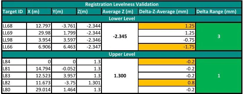
There is a tremendous benefit in using a secondary inexpensive instrument to evaluate and improve the levelness of a registration. This workflow will not replace the need for using survey control, but it is an in-between solution for small and medium size projects.